
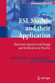

From Electronic System-Level Design to Hardware–Software Co-Design
A Model-Based Engineering Framework for RTOS, Embedded Linux, Yocto, FPGA, Automotive Diagnostics, and Smart-Grid Systems
Prepared by: IAS-Research.com
Implementation and engineering partner: KeenComputer.com
Publication date: October 2026
Document type: Technical research and engineering strategy white paper
Primary audience: Embedded-systems architects, electronics engineers, software engineers, researchers, CTOs, and SME technology leaders
Abstract
Electronic System-Level (ESL) design and hardware–software co-design offer a systematic way to engineer complex embedded and cyber-physical systems before committing to detailed hardware fabrication or software implementation. Modern systems combine microcontrollers, real-time operating systems (RTOS), embedded Linux, programmable logic, heterogeneous processors, networking, sensors, and increasingly, artificial intelligence. Designing these components independently and integrating them late can produce avoidable performance problems, timing failures, integration defects, security weaknesses, and costly architectural changes.
This white paper develops an integrated engineering framework grounded in the work of Brian Bailey, Grant Martin, and Andrew Piziali; the model-based system-design research of Daniel Gajski, Samar Abdi, Andreas Gerstlauer, and Gunar Schirner; and established research traditions in hardware–software co-design, virtual platforms, transaction-level modeling, and design-space exploration. It also identifies relevant research connections at the University of Texas at Austin and German research institutions.
The proposed framework connects requirements engineering, executable system models, hardware/software partitioning, SystemC/TLM, FPGA design, RTOS development, embedded Linux, Yocto-based product platforms, simulation, continuous integration, and hardware-in-the-loop testing. Two applied engineering programs—OBD-AI vehicle diagnostics and an AI-enabled smart-grid platform—illustrate how the same methodology can support substantially different applications.
The paper concludes with a practical workflow, toolchain recommendations, verification strategy, staged implementation roadmap, research opportunities, and a commercialization model for IAS-Research.com and KeenComputer.com.
Keywords: Electronic System-Level Design; hardware–software co-design; ESL; SystemC; transaction-level modeling; TLM; MBSE; FPGA; RTOS; embedded Linux; Yocto Project; virtual platform; QEMU; design-space exploration; OBD-AI; smart grid; cyber-physical systems; hardware/software verification.
Executive summary
The central engineering proposition is straightforward: make architecture and partitioning decisions early, evaluate them with models and measurable constraints, and verify the resulting implementation against those constraints throughout development.
Bailey, Martin, and Piziali provide a practical ESL design-flow reference that explicitly addresses specification, modeling, pre-partitioning analysis, partitioning, post-partitioning analysis, verification, and hardware/software implementation.
ScienceDirect
+1
Gajski and colleagues provide a complementary academic treatment of system modeling, synthesis, software and hardware implementation, and verification.
Springer Nature Link
The proposed IAS-Research.com framework builds on these foundations through seven engineering principles:
- Model before committing: create an executable architectural representation of the system before detailed implementation.
- Co-design hardware and software: determine which functions belong on CPUs, microcontrollers, RTOS tasks, embedded Linux, FPGA logic, or dedicated hardware.
- Explore measurable alternatives: compare latency, throughput, power, memory, cost, development effort, and verification burden.
- Use abstraction deliberately: employ high-level models for architecture exploration and progressively more detailed models for implementation and validation.
- Verify interfaces as rigorously as components: define and test timing, data ownership, error handling, synchronization, interrupts, and communications.
- Reproduce the build and test process: version the architecture, software, hardware descriptions, configurations, test cases, and evidence.
- Separate research from product claims: distinguish modeled performance from measured performance and prototypes from safety-qualified or certified products.
The business opportunity is to convert these principles into repeatable engineering services: architecture assessments, virtual-platform prototypes, embedded Linux/Yocto platforms, RTOS firmware, FPGA integration, verification automation, and managed product-lifecycle support.
1. Introduction and research problem
1.1 The growing complexity of embedded systems
Embedded computing has evolved from relatively isolated microcontroller applications into heterogeneous systems that integrate several execution environments and technologies:
- Microcontrollers and digital signal processors for sensing, acquisition, and control.
- RTOS-based firmware for tasks with bounded response-time requirements.
- Embedded Linux for networking, data management, diagnostics, security, and application services.
- FPGA and dedicated hardware for parallel processing, deterministic pipelines, and specialized interfaces.
- Virtual platforms and simulation environments for early development and architectural evaluation.
- Cloud, edge, and AI services for analytics, knowledge retrieval, predictive maintenance, and optimization.
These technologies create opportunities, but they also introduce architectural dependencies. For example, an FPGA accelerator may increase computation throughput while increasing DMA complexity, memory contention, driver effort, and verification cost. An embedded Linux gateway may simplify networking and data services but may be unsuitable for a function with a strict hard-real-time deadline unless the complete platform and scheduling design have been engineered and validated for that requirement.
The fundamental problem is therefore not merely how to implement a function. It is how to allocate functionality across hardware and software so that the complete system satisfies its requirements at acceptable cost and risk.
1.2 Why sequential development can be problematic
A conventional project may proceed as follows:
- Requirements are documented.
- Hardware is selected or designed.
- Firmware and application software are developed.
- Drivers and interfaces are integrated.
- Performance and reliability problems are discovered.
- The architecture is revised under schedule pressure.
This approach can work for relatively simple systems. For complex platforms, however, late discovery of a partitioning problem can require changes to processor selection, memory architecture, interface definitions, scheduling, FPGA logic, and application software simultaneously.
ESL and hardware–software co-design address this problem by moving selected design decisions earlier in the lifecycle. Rather than waiting for a physical prototype, engineers build models that enable architectural alternatives to be evaluated before full implementation.
The goal is not to eliminate prototypes or testing. It is to make prototypes more informed and reduce the number of expensive surprises.
1.3 Research questions
This white paper organizes the subject around six questions:
- How can ESL models support architectural decisions before detailed hardware and software implementation?
- How should functionality be partitioned among processors, RTOS tasks, embedded Linux, FPGA logic, and dedicated hardware?
- How can MBSE, SystemC/TLM, virtual platforms, and simulation support a consistent design flow?
- How should software, hardware, and system-level verification be combined?
- How can these methods be applied to OBD-AI vehicle diagnostics and smart-grid engineering?
- How can IAS-Research.com and KeenComputer.com turn the methodology into repeatable research, implementation, and commercialization services?
1.4 Scope and nature of the paper
This is a technical research and engineering-methodology white paper, based on established books, standards, research-group materials, official documentation, and a proposed engineering framework.
It does not claim that IAS-Research.com has experimentally validated every proposed workflow or that the example applications are completed products. The use cases and implementation roadmap are engineering proposals. Empirical performance claims would require measured results from actual prototypes.
2. Research foundations: Brian Bailey and ESL design methodology
2.1 The foundational ESL reference
The primary reference is:
Bailey, Brian, Grant Martin, and Andrew Piziali. ESL Design and Verification: A Prescription for Electronic System-Level Methodology. Morgan Kaufmann, 2007. ISBN 978-0-12-373551-5.
The publisher's contents identify chapters on ESL concepts, the design flow, specifications and modeling, pre-partitioning analysis, partitioning, post-partitioning analysis and debugging, verification, hardware implementation, software implementation, and implementation verification.
ScienceDirect
+1
This structure is important because it treats ESL as a connected design methodology rather than as a modeling language or a simulation tool in isolation.
The practical lesson is that the engineering team should not stop after building a high-level model. The model should support decisions that flow into hardware/software partitioning, implementation, debugging, and verification.
2.2 A systematic ESL design flow
1
1. Requirements and specification
Functions, constraints, interfaces, operating scenarios
2
2. Executable system modeling
Behavior, communication, concurrency, performance assumptions
3
3. Pre-partitioning analysis
Workload profiling, bottlenecks, alternative architectures
4
4. Hardware/software partitioning
CPU/MCU, RTOS, Linux, FPGA, dedicated logic
5
5. Post-partitioning analysis
Timing, communication overhead, memory, throughput
6
6. Implementation and integration
RTL, firmware, drivers, operating systems, applications
7
7. Verification and validation
Component tests, co-simulation, HIL, physical measurements
Feedback is expected: measured results may require changes to the model, partition, or requirements.
2.3 The importance of pre-partitioning analysis
Pre-partitioning analysis asks which parts of the system should be accelerated, which can remain in software, and which functions require dedicated interfaces or execution resources.
The analysis should consider more than computational complexity. Important questions include:
- Is the function computationally intensive or primarily limited by memory and I/O?
- Does it have a hard deadline or a statistical performance target?
- Is the workload naturally parallel?
- Does the function exchange large amounts of data with other components?
- How frequently might its algorithm or requirements change?
- Does the function need fault containment, independent verification, or a specific safety architecture?
- What is the total cost of implementation, debugging, maintenance, and future updates?
A function that is computationally expensive but changes frequently may initially be better suited to software. A stable, highly parallel function with strict throughput requirements may justify FPGA acceleration. A timing-sensitive control function may need to remain on a suitable MCU, DSP, or dedicated control device.
These are hypotheses to evaluate—not rules that replace measurement.
2.4 Post-partitioning analysis
After selecting a preliminary partition, the team must evaluate the cost of communication and integration.
For example, moving an algorithm to an FPGA can reduce computation time but introduce:
- Data-transfer latency.
- DMA setup and completion overhead.
- Buffer synchronization.
- Cache-coherency problems.
- Interrupt and driver overhead.
- FPGA resource constraints.
- Additional test cases at the hardware/software boundary.
Consequently, the correct metric is not simply accelerator execution time. It is the end-to-end time from input availability to the required output, including transfers, scheduling, synchronization, and any required post-processing.
3. Hardware–software co-design: theory and engineering practice
3.1 Definition
Hardware–software co-design is the coordinated development of a system in which functionality, execution resources, communication interfaces, and verification strategies are considered together.
Its scope includes:
- Specification co-design: defining behavior and constraints independently of a particular implementation where practical.
- Architecture co-design: selecting processors, memory, interconnects, FPGA resources, and software environments.
- Partitioning: deciding which functions execute in software and which are implemented in hardware.
- Interface co-design: defining registers, buses, interrupts, DMA, shared memory, and message protocols.
- Verification co-design: coordinating models, software tests, hardware verification, and integrated-system tests.
- Lifecycle co-design: ensuring the architecture remains maintainable, secure, testable, and updateable after deployment.
The classic literature provides complementary perspectives. Staunstrup and Wolf's Hardware/Software Co-Design: Principles and Practice addresses fundamental co-design issues, synthesis algorithms, prototyping, target architectures, and specification and verification.
Springer Nature Link
Gajski and colleagues provide a system-level treatment that integrates modeling, synthesis, and verification.
Springer Nature Link
3.2 Design-space exploration
A hardware/software architecture is rarely the only possible implementation. The engineering team should compare multiple feasible alternatives.
Consider a signal-processing workload that could execute on a processor, an FPGA, or a combination of both.
|
Criterion |
Processor-centric design |
FPGA-accelerated design |
Heterogeneous design |
|---|---|---|---|
|
Initial development |
Often simpler |
Requires hardware design and toolchain expertise |
Highest integration complexity |
|
Parallelism |
Depends on processor architecture |
Potentially extensive spatial parallelism |
Can balance workloads |
|
Flexibility |
Usually high |
Algorithm changes may require hardware redesign |
Flexible, but partition adds complexity |
|
Data movement |
May be simpler |
Can dominate end-to-end latency |
Requires careful interface and memory design |
|
Verification |
Software and platform focus |
RTL, timing, and interface verification |
Both hardware and software plus system integration |
|
Best fit |
Moderate workloads and evolving algorithms |
Stable, parallel, throughput-sensitive functions |
Mixed workloads with different performance needs |
A useful decision model is to minimize total lifecycle cost while meeting hard constraints:
\[ \min_{\mathbf{x}} C_{\text{lifecycle}}(\mathbf{x}) \]
subject to:
\[ \begin{aligned} T_{\text{response}}(\mathbf{x}) &\leq T_{\max}\\ P(\mathbf{x}) &\leq P_{\max}\\ M(\mathbf{x}) &\leq M_{\max}\\ R(\mathbf{x}) &\leq R_{\max} \end{aligned} \]
Here, \(\mathbf{x}\) represents an architecture and partition; \(T\) is response time, \(P\) is power, \(M\) is memory or resource use, and \(R\) represents a project-specific risk constraint. This is a conceptual optimization formulation, not a claim that all criteria can be reduced to precise numbers in every project.
3.3 A practical partitioning decision procedure
For every major function, the architecture team should document:
- Required behavior and inputs/outputs.
- Typical and worst-case workload assumptions.
- Response-time and throughput requirements.
- Available execution resources.
- Data-transfer and synchronization requirements.
- Power, memory, cost, and thermal limits.
- Algorithm stability and anticipated updates.
- Verification effort and safety/security implications.
- Alternative implementations and supporting evidence.
- Decision rationale and conditions that would trigger reconsideration.
The result should be an architecture decision record. It should state not only what was chosen, but why it was chosen, what alternatives were considered, and what evidence supports the decision.
4. Abstraction levels, SystemC/TLM, and virtual platforms
4.1 Why abstraction levels matter
An embedded system can be modeled at several levels:
|
Level |
Representation |
Main purpose |
|---|---|---|
|
Requirements |
Use cases, constraints, scenarios |
Define intended behavior and acceptance criteria |
|
Functional model |
Algorithms and functional blocks |
Check behavior and compare approaches |
|
Architecture model |
Processors, memories, buses, accelerators |
Evaluate resource allocation |
|
Transaction-level model |
Communication transactions and approximate timing |
Explore system architecture and data flow |
|
Cycle-accurate model |
Clock-cycle behavior and detailed interfaces |
Analyze timing-sensitive interactions |
|
RTL |
Register-transfer logic |
Synthesize and verify hardware |
|
Physical implementation |
FPGA placement/routing or ASIC implementation |
Measure implementation-level timing and resource characteristics |
|
Target system |
Real hardware, firmware, OS, and application |
Validate real operating conditions |
The team should use the least expensive model that can answer the current engineering question, then increase model fidelity when needed.
A functional model may be sufficient to compare algorithms. A transaction-level model may help compare bus architectures. RTL simulation may be required for clock-cycle behavior. Physical implementation and measurement remain necessary to establish real-world timing, power, and resource performance.
4.2 SystemC and transaction-level modeling
SystemC is a standardized language and library framework used for system-level design, modeling, and verification. IEEE Std 1666-2023 is the current published base standard identified by the IEEE and Accellera resources, with Corrigendum 1-2025 listed as a correction to that standard.
systemc.org
+2
Transaction-level modeling (TLM) represents communication at an abstraction above individual signal transitions. Instead of modeling every bus signal at the outset, a model can represent transactions such as a processor reading a register, a DMA engine transferring a buffer, or a peripheral returning data.
TLM is useful when the principal questions concern:
- Architecture and resource allocation.
- Communication volume and contention.
- Processor-to-accelerator interaction.
- Throughput and approximate timing.
- Alternative memory and interconnect designs.
- The impact of communication overhead on system performance.
TLM is not automatically cycle-accurate. Timing precision depends on the model, its timing annotations, the selected abstraction, and validation against the intended implementation.
4.3 Virtual platforms
A virtual platform is a software model of a computing platform—potentially including a processor, memory, peripherals, interconnect, and software-visible interfaces—that can support early software development and architecture exploration.
It can enable software teams to begin integration before the final hardware is available. The model may also support repeatable tests and automated execution.
However, virtual platforms differ in fidelity. A model intended for driver development may not represent cache behavior or peripheral timing accurately enough for worst-case response-time analysis.
4.4 QEMU and its appropriate role
QEMU is an open-source machine emulator and virtualizer. Its system-emulation mode can model a machine sufficiently to run a guest operating system, while user-mode emulation supports running compatible programs built for another processor architecture.
QEMU documentation
+1
For this framework, QEMU can be used to:
- Start embedded Linux development before target hardware is fully available.
- Test application startup and configuration.
- Validate selected filesystem and service behaviors.
- Exercise network services and some emulated devices.
- Run automated tests on compatible emulated targets.
QEMU must not be assumed to reproduce every physical peripheral, FPGA accelerator, timing characteristic, or target-board failure mode. Real hardware and appropriate hardware-in-the-loop testing are still required.
4.5 A recommended modeling strategy
The proposed IAS-Research.com workflow is:
- Establish functional correctness in an implementation-independent model.
- Add architecture, communication, and resource assumptions.
- Compare feasible hardware/software partitions.
- Implement selected interfaces and components.
- Run co-simulation or virtual-platform tests where supported.
- Verify RTL and software independently.
- Integrate on physical hardware.
- Compare measured behavior with model predictions.
- Calibrate the model or document its limitations.
- Preserve the model and evidence for future design changes.
This strategy uses models to guide engineering rather than treating model outputs as a substitute for physical verification.
5. Model-based systems engineering and traceability
5.1 Integrating MBSE with ESL
Model-Based Systems Engineering (MBSE) provides a structured way to represent system requirements, architecture, behavior, interfaces, and verification relationships. ESL modeling complements MBSE by introducing executable models that can evaluate aspects of the proposed architecture.
The two approaches serve different but connected purposes:
- MBSE organizes the system description and its relationships.
- Executable models test behavior and selected architectural assumptions.
- Hardware/software co-design allocates functionality across implementation resources.
- Verification engineering establishes whether requirements have been met.
- Configuration management preserves the exact versions of the design and evidence.
SysML or UML models should not automatically be treated as executable performance models. Their usefulness depends on the modeling method, tool support, and whether the model captures the behavior being evaluated.
5.2 A traceability model
Every critical requirement should connect to an architectural element, an implementation artifact, and a verification method.
Requirement
What must the system do?
Architecture element
Which component is responsible?
Interface contract
How do components communicate?
Implementation artifact
Which firmware, RTL, driver, or service realizes it?
Verification evidence
Which test, measurement, or analysis demonstrates compliance?
For example, an acquisition-latency requirement should connect to the sampling or polling mechanism, timestamp definition, driver or firmware implementation, and a test that measures the end-to-end latency under representative operating conditions.
Traceability is especially important when one requirement crosses hardware, firmware, an operating system, and an application. It helps prevent a team from verifying each component individually while missing a system-level defect.
5.3 Recommended engineering records
IAS-Research.com should consider maintaining the following artifacts for each engagement:
- Requirements and acceptance-criteria register.
- System context diagram and use-case descriptions.
- Architecture model and hardware/software allocation.
- Interface-control documents.
- Model assumptions and calibration notes.
- Architecture decision records.
- Verification plan and requirements-to-test mapping.
- Risk register, defect log, and change-impact analysis.
- Reproducible build instructions and release manifest.
These artifacts provide a reusable evidence base for research, engineering handover, maintenance, and future product development.
6. RTOS, embedded Linux, Yocto, and FPGA integration
6.1 The heterogeneous platform
Many embedded systems require more than one execution environment. A practical architecture may combine a microcontroller running an RTOS, a processor running embedded Linux, and an FPGA for selected parallel operations.
Application and system requirements
Timing · reliability · power · connectivity · maintainability
RTOS / MCU
Bounded tasks, acquisition, control, interrupt handling
Embedded Linux
Networking, storage, services, logging, update management
FPGA / dedicated logic
Parallel processing, specialized interfaces, acceleration where justified
Cross-platform integration and verification
Defined interfaces · shared timing assumptions · tests · diagnostics
This is a reference architecture, not a requirement to include every component in every product. A small diagnostic adapter may need only a microcontroller; a smart-grid gateway may require Linux plus a separate control processor; an FPGA is justified only when its benefits outweigh its cost and complexity.
6.2 RTOS engineering
An RTOS is appropriate when a system requires controlled task scheduling and predictable response behavior. The design must address more than the choice of RTOS.
Important engineering activities include:
- Task decomposition and priority assignment.
- Worst-case execution-time assumptions and measurement.
- Interrupt latency and interrupt-service design.
- Shared-resource synchronization.
- Priority inversion and resource contention.
- Watchdog strategy and failure recovery.
- Stack sizing and memory constraints.
- Timing analysis under representative workloads.
- Fault injection and long-duration stability testing.
FreeRTOS provides a widely used RTOS implementation and official technical documentation. FreeRTOS documentation. A project should choose an RTOS based on hardware support, licensing, timing needs, security, ecosystem, and lifecycle requirements—not familiarity alone.
6.3 Embedded Linux and Yocto Project
Embedded Linux is appropriate for systems that need a richer application environment, networking, filesystems, service management, data handling, and a broad software ecosystem.
The Yocto Project provides tools and methods for building custom Linux-based systems for embedded products and targeted deployment environments. Its official documentation describes layers, build workflows, Poky, OpenEmbedded, development practices, and reference manuals.
The Yocto Project ® dev documentation
+2
A disciplined Yocto workflow should include:
- Select a supported target board and baseline release.
- Establish the build host, source-control structure, and required dependencies.
- Organize configuration and recipes into maintainable layers.
- Integrate the kernel, device tree, drivers, boot configuration, and root filesystem.
- Define package selection and application integration.
- Configure security updates, credentials, logging, and device identity.
- Build reproducible release candidates.
- Run emulated tests where supported.
- Test the image on target hardware.
- Archive source revisions, configuration, build logs, test results, and release artifacts.
Recommended official resources:
- Yocto Project overview — project purpose and ecosystem.
- Yocto overview and concepts manual — architecture and build concepts.
- Yocto documentation index — quick build, development, and reference manuals.
- QEMU documentation — emulation and virtual-machine operation.
Documentation should be pinned to the Yocto release actually selected for the project. Development documentation may describe features that are not present in an older stable release.
6.4 FPGA-based systems
FPGA logic can implement parallel datapaths, protocol engines, specialized signal processing, or accelerators for workloads that benefit from spatial parallelism.
A responsible FPGA design flow includes:
- Define the hardware/software boundary and interface contract.
- Establish a reference algorithm or behavioral model.
- Implement the RTL using the selected hardware description language.
- Verify functionality through simulation and assertions.
- Synthesize the design and inspect resource utilization.
- Perform timing analysis and physical implementation.
- Integrate registers, interrupts, DMA, and driver interfaces.
- Test under representative traffic and concurrent workloads.
- Measure end-to-end system performance.
- Archive the source, constraints, tool versions, reports, and bitstream.
An accelerator should be evaluated against a software baseline using a consistent workload. Measurements should include transfer overhead, end-to-end latency, throughput, resource use, and power where those metrics are important.
6.5 Interface contracts between execution environments
The most error-prone boundaries often occur between components rather than inside them. Every cross-platform interface should specify:
- Data formats, units, scaling, and byte order.
- Register definitions and valid access sequences.
- Ownership and lifetime of shared buffers.
- Interrupt, DMA, and completion semantics.
- Synchronization and timeout behavior.
- Error reporting and recovery.
- Version compatibility and update rules.
- Security boundaries and permissions.
- Timing expectations and the measurement points used to verify them.
A hardware/software interface specification should be treated as a controlled engineering artifact, not merely as comments embedded in source code.
7. Verification, validation, and DevOps for hardware/software co-design
7.1 Verification must span the complete system
A successful unit test does not prove that the integrated system meets its requirements. A function can pass its software tests but fail because of interrupt timing, data loss, an incorrect register definition, an overloaded communication path, or a mismatch between modeled and physical behavior.
A complete verification strategy should cover several levels.
|
Verification level |
Primary purpose |
Example evidence |
|---|---|---|
|
Requirements review |
Establish completeness and consistency |
Approved requirements baseline |
|
Model verification |
Check model behavior and assumptions |
Model tests and review records |
|
Software unit testing |
Check software components |
Automated test results |
|
RTL verification |
Check hardware logic |
Simulation, assertions, coverage reports |
|
Interface verification |
Check communication across boundaries |
Protocol and integration tests |
|
Co-simulation |
Examine combined hardware/software behavior |
Coordinated simulation results |
|
Virtual-platform testing |
Start software before physical hardware is ready |
Boot, service, and application test results |
|
Hardware-in-the-loop |
Test interactions with a real-time or representative plant/environment |
Timing, fault-response, and integration evidence |
|
Physical-system validation |
Confirm operation on the intended hardware |
Measured results and test reports |
|
Regression testing |
Detect unintended changes |
Versioned repeatable test suite |
7.2 Continuous integration for embedded platforms
Continuous integration can make hardware/software co-design more reproducible by automating the tasks that can reliably be automated.
A proposed pipeline is:
Source control
Firmware · RTL · models · recipes · configuration
Static checks
Formatting · linting · security and dependency checks
Automated builds
Software binaries · Linux images · FPGA synthesis where feasible
Simulation and unit tests
Model tests · software tests · RTL regressions
Integration and target tests
Virtual platform · board tests · HIL
Release evidence
Build manifest · test results · known limitations · artifacts
Not every test belongs in every commit. FPGA synthesis, full Linux image creation, hardware-in-the-loop execution, and extended reliability tests may be scheduled differently according to cost and execution time.
7.3 DevOps versus embedded product engineering
DevOps principles can support embedded development, but the product pipeline must account for hardware-specific constraints. A passing CI pipeline does not establish that a physical system is safe, compliant, or robust under all operating conditions.
The release process should retain:
- Source revisions and dependency manifests.
- Compiler, synthesis, and build-tool versions.
- Kernel, RTOS, firmware, and FPGA configuration.
- Test environment and hardware revision.
- Test results, coverage, and unresolved defects.
- Release-signing and update procedures.
- Known limitations and rollback instructions.
This creates a reproducible basis for maintenance and helps teams investigate whether a field issue is associated with a software change, hardware revision, configuration, or environmental condition.
8. International research context: UT Austin and Germany
8.1 University of Texas at Austin
Andreas Gerstlauer's research program describes electronic system-level design of embedded computing systems, with emphasis on system-level design automation, methodologies, technologies, and tools. The research includes the System-on-Chip Design Environment and heterogeneous multiprocessor systems spanning hardware/software boundaries.
users.ece.utexas.edu
This research is relevant to the proposed paper because it connects high-level system specifications to implementation architectures, rather than treating hardware and software as independent design activities.
Recommended resources
- Andreas Gerstlauer — research overview
- Research publications
- UT Center for Embedded Computer Systems technical reports
For publication, specific UT reports and papers should be cited by their full title, authors, year, and report or publication identifier after checking the original document.
8.2 German research: Technical University of Munich
The Technical University of Munich's Design of Electronic Circuits and Systems research is a relevant reference point for hardware/software co-design, virtual prototyping, and heterogeneous embedded architectures. Its research areas include system design and acceleration-related topics. See the official TUM research overview.
The connection to this paper is methodological: architectural decisions should be explored through appropriate models and prototypes before expensive implementation commitments.
8.3 German research: Fraunhofer IIS and the ESI Application Center
The Fraunhofer IIS Embedded Systems Initiative (ESI) Application Center combines industrial development expertise with research from Friedrich-Alexander-Universität Erlangen-Nürnberg (FAU). Its stated areas include multicore systems, wireless communication, design methodologies, and hardware/software co-design. It describes feasibility studies, prototype development, and application-oriented testing.
iis.fraunhofer.de
+1
Official resource: Fraunhofer IIS ESI Application Center.
This is particularly relevant to a research-to-product model for SMEs: assess feasibility, compare architectures, develop a prototype, test it in a representative environment, and then make a production decision.
8.4 German research: Fraunhofer HHI
Fraunhofer Heinrich Hertz Institute's Embedded Systems Group describes efficient co-design of hardware, software, and overall system architecture, including hardware-accelerated coprocessors, many-core platforms, profiling, simulation, and rapid prototyping.
hhi.fraunhofer.de
Official resource: Fraunhofer HHI Embedded Systems Group.
8.5 How to use these research references responsibly
These institutions provide relevant methodological and research examples. Their work should be cited to support specific statements about their documented research, not as evidence that they endorse this white paper or have partnered with IAS-Research.com.
The paper's proposed contribution is a practical synthesis of established methodologies and a reusable application framework for embedded engineering. A claim of novelty at the level of academic research would require a systematic literature review, comparison with existing frameworks, and empirical evaluation.
9. Application case study A: OBD-AI vehicle diagnostics
9.1 Problem statement
OBD-AI is a proposed intelligent vehicle-diagnostics platform combining vehicle telemetry, diagnostic trouble codes (DTCs), service-manual knowledge, and AI-assisted troubleshooting.
A useful system must do more than retrieve a trouble code or generate a plausible explanation. It must preserve data integrity, interpret vehicle-specific context, identify uncertainty, link recommendations to supporting evidence, and guide the user toward appropriate tests.
Hardware/software co-design determines where acquisition, protocol handling, local processing, knowledge retrieval, and diagnostic inference should execute.
9.2 Proposed reference architecture
Vehicle and ECU interfaces
OBD-II connection · supported diagnostic services · live parameters
Acquisition firmware
Protocol handling · timestamps · validation · buffering
Optional MCU / RTOS
Bounded acquisition and interface tasks where required
Embedded Linux gateway
Connectivity · local cache · logging · secure communications
Diagnostic and knowledge services
DTC context · service manuals · retrieval-augmented language model
Technician-facing application
Ranked hypotheses · evidence · test procedures · recorded findings
This architecture is a reference design. The MCU/RTOS and Linux gateway may be combined, separated, or omitted depending on the selected adapter and product requirements.
9.3 Hardware/software allocation
Acquisition and interface layer
The lowest layer is responsible for correct communication with the supported vehicle interface. It should validate frames and responses, maintain timestamps, handle timeouts, and prevent malformed or stale data from silently propagating.
Embedded firmware
An MCU may perform polling, low-level protocol tasks, buffering, and bounded operations. If those functions do not require a separate RTOS or dedicated controller, a simpler implementation may be more economical.
Linux gateway
A gateway can provide networking, storage, diagnostics, device management, and application integration. Yocto may be appropriate when a custom, maintainable embedded Linux distribution is needed.
Diagnostic intelligence
The RAG-LLM layer should retrieve relevant documentation and combine it with validated vehicle data and diagnostic rules. It should distinguish observed facts from hypotheses and recommend confirmatory tests rather than declaring a component defective based on a DTC alone.
9.4 Verification plan
The initial OBD-AI demonstrator should include tests for:
- Correct handling of supported diagnostic messages.
- Missing, malformed, repeated, and out-of-order data.
- Timestamp consistency and stale-data detection.
- Incorrect or incomplete vehicle context.
- Retrieval accuracy and provenance of supporting documents.
- Distinguishing measured facts from AI-generated hypotheses.
- Offline behavior and recovery after communications loss.
- Logging, privacy, access control, and software updates.
- Reproducibility of diagnostic output for a fixed test case and knowledge base.
- Prevention of unauthorized or unsafe vehicle-control actions.
9.5 Standards and resources
The protocol baseline should be determined by the vehicle and services supported. Two relevant SAE standards are:
The implementation team must consult the applicable standards' complete requirements and licensing/access conditions. Support for a protocol does not imply compatibility with every vehicle or manufacturer-specific diagnostic function.
9.6 Potential deliverables
IAS-Research.com could produce the system architecture, data and knowledge model, partitioning study, diagnostic evidence model, and verification strategy.
KeenComputer.com could implement the gateway, firmware, drivers, Linux image, test harness, application interfaces, and deployment workflow.
A commercially credible first release should target a bounded set of vehicle models, supported diagnostic services, and documented test scenarios. Broad vehicle compatibility should be demonstrated rather than assumed.
10. Application case study B: AI-enabled smart-grid systems
10.1 Problem statement
A smart-grid platform may integrate photovoltaic generation, battery storage, inverters, grid sensors, power-quality monitoring, communications, and supervisory analytics.
The challenge is to separate functions that require deterministic control and protection behavior from functions that benefit from richer operating systems and data-intensive software.
Hardware/software co-design can help identify an architecture that meets timing, performance, security, and maintenance requirements while avoiding unnecessary complexity.
10.2 Proposed reference architecture
Electrical plant
PV · storage · converters · sensors · grid interface
Deterministic control
MCU/DSP · RTOS · control loops · protection interfaces
Hardware acceleration
FPGA · parallel signal processing · specialized datapaths where justified
Embedded Linux gateway
Telemetry · data logging · protocol translation · secure updates
Supervisory analytics and AI
Forecasting · anomaly analysis · operator decision support · reporting
The separation between control and supervisory layers is an architectural principle, not a substitute for a system safety analysis. Some systems may require additional controllers, redundant protection, isolation, or other independently engineered safeguards.
10.3 Role of RTOS and FPGA
An RTOS-based controller may execute bounded control tasks, coordinate sensing and actuation, and manage communication with adjacent devices.
FPGA logic may be considered for parallel signal processing, high-rate acquisition, or specialized timing-sensitive operations when the requirements justify it. Its use should be supported by workload profiling and measurements.
Fast control and protection functions must be designed and verified against their actual timing and safety requirements. A general-purpose AI model should not be inserted into a hard-real-time protection path without a separately justified and validated architecture.
10.4 Role of embedded Linux and AI
An embedded Linux gateway can aggregate data, log events, translate protocols, manage connectivity, and deliver updates. A supervisory AI service can assist with anomaly investigation, forecasting, and operator decision support.
AI recommendations should be presented with relevant evidence, limitations, and confidence or uncertainty information. They should not bypass independently engineered protection functions or replace mandatory operator and engineering procedures.
10.5 Modeling and verification strategy
A smart-grid demonstrator may combine different modeling environments:
- MATLAB/Simulink for control-system and algorithm development.
- PSCAD for electromagnetic-transient and power-system studies where appropriate.
- SystemC/TLM for selected computing and communication architecture questions.
- RTL simulation and FPGA implementation tools for hardware logic.
- Virtual platforms and software simulation for embedded application development.
- HIL and physical tests for integrated control and plant behavior.
These models represent different aspects of the system. Their interfaces, sampling assumptions, timing, and synchronization must be explicitly defined when they are coupled.
Verification should cover timing and jitter, sensor failures, communication delays and loss, restart and recovery, control-interface behavior, model-to-measurement discrepancies, cybersecurity, and sustained operation.
Applicable grid interconnection, electrical safety, power-quality, and cybersecurity requirements must be identified for the intended jurisdiction and product. The use of a modeling tool or completion of a simulation does not establish compliance by itself.
11. Comparative analysis of the two application programs
|
Dimension |
OBD-AI |
Smart-grid platform |
|---|---|---|
|
Primary environment |
Vehicle diagnostics and service workflow |
Electrical energy and control environment |
|
Acquisition |
OBD-II data, diagnostic services, supported vehicle signals |
Electrical sensors, converter signals, telemetry |
|
Embedded processing |
Protocol handling, buffering, validation |
Sampling, local control, data aggregation |
|
RTOS role |
Optional, depending on adapter architecture and timing needs |
Potentially important for bounded control tasks |
|
Embedded Linux role |
Gateway, diagnostics, storage, connectivity |
Gateway, logging, protocol translation, supervisory services |
|
FPGA role |
Only when a demonstrated workload justifies it |
Potentially useful for high-rate or parallel signal processing |
|
AI role |
Evidence-grounded diagnostic support |
Supervisory analytics and operator decision support |
|
Key verification concern |
Diagnostic evidence, data integrity, supported vehicle behavior |
Timing, protection boundaries, physical behavior, system recovery |
|
Deployment risk |
Incorrect diagnosis or unsupported vehicle behavior |
Physical damage, grid disturbance, or unsafe control behavior |
|
Initial pilot |
A bounded set of vehicles and diagnostic scenarios |
A defined plant model, controller, and limited test scenarios |
The common engineering platform is requirements traceability, architecture modeling, partition analysis, interface contracts, automated builds, layered verification, and documented evidence. The application-specific models and acceptance criteria remain different.
12. An integrated research and implementation methodology
The following methodology is proposed for IAS-Research.com and KeenComputer.com engagements.
Phase 1 — Requirements and feasibility
Objectives
- Identify the customer problem and operating environment.
- Define functional and non-functional requirements.
- Establish safety, security, privacy, and compliance constraints.
- Identify candidate hardware and software platforms.
- Create a baseline architecture and risk register.
Deliverables
Requirements register, system context, initial architecture, feasibility assessment, and measurable acceptance criteria.
Phase 2 — Executable modeling and architecture exploration
Objectives
- Build a functional or system-level model.
- Define major components and their interfaces.
- Identify bottlenecks and critical timing paths.
- Compare processor-centric, FPGA-assisted, and heterogeneous alternatives.
- Document assumptions and model limitations.
Deliverables
Executable model where appropriate, architecture alternatives, partitioning report, and architecture decision records.
Phase 3 — Prototype implementation
Objectives
- Develop selected firmware and hardware components.
- Implement drivers, interfaces, and services.
- Create the RTOS or embedded Linux environment.
- Develop FPGA logic where justified.
- Establish automated build and unit-test workflows.
Deliverables
Prototype hardware/software integration, versioned source, build instructions, initial test results, and documented limitations.
Phase 4 — Integration and verification
Objectives
- Execute interface and regression tests.
- Compare implementation behavior with the model.
- Measure performance under representative loads.
- Conduct fault injection and recovery tests.
- Test on physical hardware and use HIL where appropriate.
Deliverables
Verification matrix, measured performance results, defect register, model-correlation report, and release-candidate evidence.
Phase 5 — Demonstration and commercialization
Objectives
- Demonstrate the bounded use case.
- Evaluate technical acceptance criteria.
- Estimate production, support, and maintenance costs.
- Identify remaining engineering and compliance work.
- Define the next product increment.
Deliverables
Demonstrator, technical report, commercial feasibility assessment, product roadmap, and proposed maintenance plan.
Indicative 12-week pilot
|
Weeks |
Activity |
Decision gate |
|---|---|---|
|
1–2 |
Requirements, use case, and feasibility |
Approve bounded scope |
|
3–4 |
Modeling, architecture, and partition analysis |
Select preferred architecture |
|
5–8 |
Prototype implementation |
Demonstrate component integration |
|
9–10 |
Verification and performance measurements |
Assess acceptance criteria |
|
11–12 |
Demonstration and commercialization review |
Decide whether to continue |
This schedule is an indicative planning framework, not a delivery guarantee. A small OBD-AI gateway demonstrator and a smart-grid HIL demonstrator can have very different hardware, laboratory, and compliance requirements.
13. Detailed bibliography: books, research papers, standards, and technical resources
This bibliography is intended to support the publication, subsequent technical articles, and further research by IAS-Research.com. It distinguishes foundational books, research publications, standards, and practical implementation documentation.
13.1 Foundational books on ESL and hardware–software co-design
[1] Bailey, B., Martin, G., and Piziali, A. (2007). ESL Design and Verification: A Prescription for Electronic System-Level Methodology. Morgan Kaufmann.
Primary reference
ISBN 978-0-12-373551-5.
Why it matters: The central practical reference for the paper's ESL workflow, including specification, modeling, pre-partitioning analysis, partitioning, post-partitioning analysis, verification, and implementation.
Recommended reading: Chapters 1–6 for concepts and flow; Chapters 7–10 for analysis, partitioning, and verification; Chapters 11–13 for hardware/software implementation and implementation verification.
Publisher page and table of contents
[2] Gajski, D. D., Abdi, S., Gerstlauer, A., and Schirner, G. (2009). Embedded System Design: Modeling, Synthesis and Verification. Springer.
DOI: 10.1007/978-1-4419-0504-8.
Why it matters: A strong academic foundation for system modeling at multiple abstraction levels, hardware/software co-design, system synthesis, embedded software and hardware synthesis, and verification.
Recommended reading: Chapters on system design methodologies, modeling, system synthesis, software synthesis, hardware synthesis, verification, and embedded design practice.
Springer Nature Link
[3] Staunstrup, J., and Wolf, W., eds. (1997). Hardware/Software Co-Design: Principles and Practice. Springer.
DOI: 10.1007/978-1-4757-2649-7.
Why it matters: Covers co-design fundamentals, hardware/software co-synthesis, prototyping, emulation, target architectures, specification, and verification. It provides historical and conceptual context for modern heterogeneous embedded platforms.
Springer Nature Link
[4] De Micheli, G., and Sami, M., eds. (1996). Hardware/Software Co-Design. Kluwer Academic Publishers.
DOI: 10.1007/978-94-009-0187-2.
Why it matters: A historical research collection covering embedded and communication systems, performance analysis, automotive electronics, FPGA prototyping, hardware/software synthesis, and design automation. It is useful for tracing the development of co-design methods.
Springer Nature Link
[5] Balarin, F., Chiodo, M., Giusto, P., Hsieh, H., Jurecska, A., Lavagno, L., Passerone, C., Sangiovanni-Vincentelli, A., Suzuki, K., and Tabbara, B. (1997). Hardware-Software Co-Design of Embedded Systems: The POLIS Approach. Springer.
DOI: 10.1007/978-1-4615-6127-9.
Why it matters: Explores formal models, co-design, synthesis, interfaces, RTOS integration, and verification. It is particularly relevant to embedded control systems where correctness and timing matter.
Springer Nature Link
[6] Ghenassia, F., ed. (2005). Transaction-Level Modeling with SystemC: TLM Concepts and Applications for Embedded Systems. Springer.
Why it matters: A useful complementary reference for transaction-level abstraction, communication modeling, virtual prototyping, and system-level simulation. Use it alongside the current SystemC standard and current implementation documentation.
13.2 Additional books for architecture, embedded software, and real-time systems
The following books extend the core ESL literature into implementation and operational engineering.
|
Reference |
Main contribution to the paper |
Recommended use |
|---|---|---|
|
Hennessy, J. L., and Patterson, D. A. Computer Architecture: A Quantitative Approach. Morgan Kaufmann; consult the edition appropriate to the project. |
Performance analysis, memory hierarchy, parallelism, processor architecture. |
Evaluating processor-centric and heterogeneous alternatives. |
|
Marwedel, P. Embedded System Design: Embedded Systems Foundations of Cyber-Physical Systems. Springer; consult the edition available to the research team. |
Embedded system architecture, modeling, implementation, and optimization. |
Broadening the theoretical background beyond ESL. |
|
Liu, J. W. S. (2000). Real-Time Systems. Prentice Hall. |
Scheduling, deadlines, real-time system concepts. |
Developing timing requirements and RTOS verification plans. |
|
Kopetz, H. (2011). Real-Time Systems: Design Principles for Distributed Embedded Applications, 2nd ed. Springer. |
Distributed real-time systems, fault tolerance, and temporal behavior. |
Timing and communication architecture in cyber-physical systems. |
|
Wolf, W. (2001). Computers as Components: Principles of Embedded Computing System Design. Morgan Kaufmann. |
Embedded processors, system architecture, hardware/software integration. |
Practical background for engineers moving from software to system architecture. |
|
Lee, E. A., and Seshia, S. A. Introduction to Embedded Systems: A Cyber-Physical Systems Approach. Available through the authors' educational resources. |
Modeling, computation, and cyber-physical system behavior. |
Connecting software execution with physical processes. |
For publication, bibliographic details such as edition, year, publisher, and ISBN should be checked against the edition actually cited. Different editions of several of these textbooks exist.
13.3 Academic research and institutional resources
These are useful starting points for a literature review. The publication lists should be searched for the specific subject under investigation; a research-group page is not a substitute for citing the individual paper that supports a claim.
|
Resource |
Relevance |
Link |
|---|---|---|
|
Andreas Gerstlauer, UT Austin — research overview |
ESL, system-level design automation, heterogeneous SoCs |
|
|
Gerstlauer — publications |
Primary papers for system modeling, synthesis, and design automation |
|
|
UT Center for Embedded Computer Systems |
Technical reports and research artifacts |
|
|
Technical University of Munich — electronic circuits and systems |
Hardware/software co-design and electronic system research |
|
|
Fraunhofer IIS — ESI Application Center |
Industrially oriented embedded systems and co-design |
|
|
Fraunhofer HHI — Embedded Systems Group |
Hardware acceleration, multicore systems, profiling, and prototyping |
Recommended literature-review procedure
For each research topic, search for individual papers on:
- Hardware/software partitioning and co-synthesis.
- Design-space exploration and multi-objective optimization.
- SystemC/TLM virtual platforms.
- Model calibration and correlation with physical measurements.
- FPGA/processor co-design and accelerator interfaces.
- Real-time scheduling and mixed-criticality systems.
- Hardware/software co-verification.
- Embedded Linux and virtual-platform integration.
- Hardware/software co-design for automotive systems.
- Real-time control and verification of power-electronic systems.
Prioritize peer-reviewed journal and conference papers, standards, and original technical reports. For each selected paper, record the exact title, authors, year, venue, DOI or stable URL, problem addressed, methodology, evidence, limitations, and relevance to the IAS-Research.com framework.
13.4 Standards and authoritative technical documentation
[7] IEEE Std 1666-2023 — Standard SystemC Language Reference Manual
SystemC's principal language standard, including its standardization history and the listed 2025 corrigendum.
- IEEE standards record
- SystemC standards and implementations
- Accellera announcement and access information
These sources identify IEEE 1666-2023 and its corrigendum.
systemc.org
+2
[8] Yocto Project documentation
The authoritative starting point for building and maintaining custom embedded Linux distributions.
The overview manual covers the layer model, build workflow, Poky, OpenEmbedded, and development concepts. Select documentation matching the release used in the actual project.
The Yocto Project ® dev documentation
+2
[9] QEMU documentation
QEMU supports system emulation and user-mode emulation. It is useful for selected software-development and virtual-platform tasks, but it does not reproduce every target-board timing or peripheral behavior.
QEMU documentation
+1
[10] FreeRTOS documentation
- Official FreeRTOS documentation
Use for RTOS concepts, kernel APIs, task scheduling, synchronization, and platform-specific implementation guidance. Select the version and port appropriate to the target.
[11] SAE J1979 and SAE J1979-2
These are relevant to the OBD-AI example. The applicable edition and scope should be confirmed for the vehicle, diagnostic service, and intended product.
13.5 Practical tools and repositories
The following resources can support reproducible implementation. Their inclusion is a toolchain recommendation, not an endorsement or guarantee of fitness for a particular safety-critical application.
|
Tool or resource |
Purpose |
Website |
|---|---|---|
|
SystemC |
System-level modeling and verification |
|
|
QEMU |
Processor and machine emulation |
|
|
Yocto Project |
Custom embedded Linux builds |
|
|
FreeRTOS |
RTOS kernel and embedded development |
|
|
Zephyr Project |
Open-source RTOS and embedded ecosystem |
|
|
Renode |
Virtual prototyping and automated testing for supported embedded platforms |
|
|
Verilator |
Open-source Verilog/SystemVerilog simulation and linting |
|
|
GTKWave |
Viewing supported digital waveform formats |
|
|
OpenROAD |
Open-source RTL-to-GDS implementation-flow resources |
|
|
Git |
Source control and collaboration |
|
|
CMake |
Cross-platform build configuration |
|
|
pytest |
Automated Python testing |
Tool selection depends on target architecture, license compatibility, model fidelity, available device support, team expertise, and project requirements. Some tools can be combined, while others address overlapping use cases and should be evaluated before committing to a common pipeline.
13.6 Suggested literature-review matrix
IAS-Research.com can use this matrix when expanding the white paper into a deeper academic or applied research program.
|
Research theme |
Foundational source |
Question to investigate |
|---|---|---|
|
ESL methodology |
Bailey, Martin, and Piziali |
How does early analysis change design decisions and verification effort? |
|
Model-based design |
Gajski et al. |
Which abstraction level is sufficient for each architectural decision? |
|
Hardware/software co-design |
Staunstrup and Wolf |
Which partitioning strategies best address conflicting system constraints? |
|
Virtual platforms |
QEMU and SystemC literature |
What behavior can be validated virtually, and what requires physical hardware? |
|
RTOS and real-time design |
Liu; Kopetz; RTOS documentation |
How should timing assumptions be verified under realistic load and faults? |
|
Embedded Linux |
Yocto Project documentation |
How can product images be maintained and reproduced across releases? |
|
FPGA implementation |
HDL tools and implementation literature |
When does acceleration improve end-to-end performance after integration costs? |
|
Automotive diagnostics |
SAE J1979 and J1979-2 |
How can data integrity and diagnostic-service compatibility be established? |
|
Smart-grid engineering |
Power-system modeling and relevant standards |
How can the control architecture be verified across computing and physical models? |
14. Proposed research contributions and future work
This white paper does not claim a new hardware/software co-design algorithm. Its contribution is a structured, applied framework that connects established ESL methods to implementation and operational practices, with two concrete engineering programs.
The next research stage should evaluate that framework empirically.
14.1 Research work package A: reproducible co-design methodology
Develop a reference project containing:
- A requirements and architecture template.
- A documented hardware/software partition.
- A SystemC/TLM or other appropriate executable model.
- A baseline software implementation.
- One alternative implementation, such as an FPGA accelerator where justified.
- Automated verification tests.
- A report comparing modeled and measured results.
The research question is whether early architecture exploration identifies important integration and performance risks before they become expensive to correct.
14.2 Research work package B: model-to-hardware correlation
Select a bounded workload and compare the model's predictions with the physical implementation.
Potential measurements include end-to-end latency, throughput, resource use, memory footprint, power, and recovery behavior. The experiment should define measurement conditions, repeatability, uncertainty, and known model limitations.
The result should be a model-correlation report—not simply a claim that simulation is accurate.
14.3 Research work package C: OBD-AI evaluation
Build a controlled diagnostic dataset containing known vehicle configurations, supported diagnostic data, documented faults or test scenarios, and relevant technical references.
Evaluate:
- Correct parsing and data validation.
- Retrieval of relevant source material.
- Accuracy and completeness of diagnostic hypotheses.
- Traceability of claims to evidence.
- Appropriate handling of missing information.
- Ability to distinguish confirmed observations from unverified explanations.
- Reproducibility across software and knowledge-base versions.
The evaluation should report errors and limitations, not only successful demonstrations.
14.4 Research work package D: smart-grid model integration
Select a specific bounded use case, such as power-quality monitoring or a limited converter-control demonstrator. Define the physical plant model, computing architecture, sampling assumptions, interface timing, and validation procedure.
Compare model outputs with suitable reference calculations, HIL results, or physical measurements. Any claims about protection behavior, electrical safety, or grid compliance must be supported by the relevant standards and engineering evidence.
14.5 Research work package E: automated engineering evidence
Investigate how CI/CD and configuration management can preserve traceability across requirements, models, firmware, RTL, Linux images, and test reports.
Potential outputs include:
- Versioned architecture decision records.
- Automated model and software tests.
- Reproducible embedded Linux builds.
- FPGA build and verification reports.
- Machine-readable requirements-to-test mappings.
- Release evidence bundles.
This work could provide a reusable foundation for SME engineering projects, where limited budgets make reproducibility and reuse especially valuable.
15. Strategic role of IAS-Research.com and KeenComputer.com
The technical framework supports a complementary research and implementation model.
15.1 IAS-Research.com: research, architecture, and engineering advisory
IAS-Research.com can position itself as the research and systems-architecture arm for organizations that need to evaluate complex embedded-system choices before investing in full implementation.
Potential services include:
- ESL and hardware/software co-design feasibility studies.
- MBSE and requirements architecture.
- SystemC/TLM and virtual-platform modeling.
- Architecture trade-off analysis and partitioning studies.
- RTOS, embedded Linux, and FPGA architecture reviews.
- Verification strategy and model-correlation studies.
- Technical white papers and engineering research reports.
- OBD-AI and smart-grid proof-of-concept design.
The key commercial output is not merely a document or diagram. It is an evidence-backed decision that reduces uncertainty about what should be built, how it should be verified, and which risks remain.
15.2 KeenComputer.com: implementation, integration, and operations
KeenComputer.com can implement the architectures selected through research and feasibility work.
Potential services include:
- Embedded Linux and Yocto platform engineering.
- RTOS firmware, drivers, and interface development.
- FPGA integration and software/hardware testing.
- QEMU-based software testing and virtual-platform integration where supported.
- Automated builds, regression testing, and CI/CD.
- Secure configuration, device management, logging, and update workflows.
- System integration, deployment, maintenance, and lifecycle support.
The commercial value is a working, maintainable implementation supported by test results, versioned artifacts, and documented operational procedures.
15.3 A joint engagement model
Customer challenge
Performance · complexity · risk · maintainability · cost
IAS-Research.com
Research · architecture · models · partitioning · verification plan
KeenComputer.com
Firmware · embedded Linux · FPGA integration · automated tests · deployment
Demonstrated engineering result
Working prototype · measured results · documented limitations · next-stage plan
This relationship should be presented as the proposed operating model of the two organizations, not as an assertion of an external partnership or an independently validated commercial track record.
15.4 Commercialization and intellectual property
Before starting a joint project, the organizations and customer should agree on:
- Ownership of pre-existing intellectual property.
- Rights to project-specific source code, models, and hardware designs.
- Licensing obligations for third-party and open-source components.
- Rights to reuse generic templates and non-confidential engineering methods.
- Confidentiality and publication approval.
- Acceptance criteria, milestones, and change-control procedures.
- Support, maintenance, and security-update responsibilities.
This is particularly important where reusable architecture templates, diagnostic knowledge models, embedded Linux layers, or hardware interfaces may be valuable across multiple future projects.
16. Conclusion
ESL design and hardware–software co-design provide a practical framework for controlling complexity in modern embedded systems. Bailey, Martin, and Piziali's methodology emphasizes the flow from specification and modeling through analysis, partitioning, implementation, and verification. Gajski and colleagues provide a complementary model-based treatment of synthesis and verification. Research at UT Austin and German institutions offers relevant examples of system-level design automation, embedded-system architecture, virtual prototyping, and hardware/software co-design.
The proposed IAS-Research.com framework integrates these foundations with MBSE, SystemC/TLM, virtual platforms, RTOS development, embedded Linux, Yocto, FPGA implementation, automated testing, and physical validation.
OBD-AI and smart-grid engineering demonstrate how a common co-design methodology can serve different application domains. In both cases, the architecture should be selected from explicit requirements and measured trade-offs rather than from assumptions that a particular processor, operating system, accelerator, or AI technique is inherently superior.
For IAS-Research.com, the opportunity is to turn the research into repeatable architecture, modeling, and verification services. For KeenComputer.com, it is to implement those architectures as working, maintainable systems with reproducible builds and documented evidence.
The recommended starting point is a bounded demonstrator with a clear acceptance criterion, an executable model where appropriate, one documented hardware/software partition, and a verification plan that includes measurements on the intended implementation.
The long-term objective is a reusable engineering practice that connects research, architecture, implementation, verification, and commercialization—reducing avoidable integration risk while making complex embedded-system development more transparent and repeatable.
Publication checklist for IAS-Research.com
Before publishing, I recommend completing the following editorial and technical checks.
Editorial readiness
0 of 10
Confirm author attribution, publication date, and IAS-Research.com branding.
Verify the bibliographic details and edition of every cited book.
Add exact titles, authors, publication venues, years, and DOI links for individual academic papers cited in the final reference list.
Confirm that every institutional research claim is supported by the relevant original source.
Review the current applicable editions of standards and tool documentation.
Clearly distinguish established research findings from proposed IAS-Research.com methods.
Label OBD-AI and smart-grid architectures as proposed use cases unless actual implementation results are available.
Add diagrams with captions, numbering, and source or authorship attribution.
Include a publication date, revision number, copyright statement, and contact or inquiry link.
Review technical accuracy, accessibility, SEO metadata, and internal links before publishing.
Suggested SEO metadata
SEO title
ESL Design and Hardware–Software Co-Design | IAS Research
Copy SEO title
Meta description
Explore ESL design, hardware–software co-design, SystemC/TLM, RTOS, embedded Linux, Yocto, FPGA, OBD-AI diagnostics, and smart-grid engineering.
Copy meta description
Primary keywords
Electronic System-Level Design, hardware-software co-design, SystemC TLM, embedded systems engineering, FPGA, RTOS, Yocto Project, embedded Linux, virtual platforms, OBD-AI, smart-grid engineering
Copy keywords
Recommended publication approach: publish the white paper as a canonical IAS-Research.com article, with the bibliography and official resource links preserved. Then create supporting technical articles on SystemC/TLM and virtual platforms, RTOS versus embedded Linux, Yocto-based product development, FPGA acceleration, OBD-AI architecture, and smart-grid co-design. Link each supporting article back to this central white paper so readers can move from the overall methodology into practical implementation topics.
--------------
Addendum: Hardware–Software Co-Design as the Core of the ESL Research Paper
Hardware–software co-design should be a central methodology in the paper on Electronic System-Level (ESL) design, connecting Brian Bailey’s ESL design and verification principles with UT Austin research, German research in electronic design automation, and the practical engineering programs of IAS-Research.com and KeenComputer.com.
The key principle is to design the hardware and software as one system, evaluate alternative partitions early, and verify their behavior across abstraction levels before committing to expensive implementation decisions.
1. Hardware–software co-design within ESL
Hardware–software co-design is the coordinated specification, modeling, partitioning, implementation, and verification of a system whose functions execute across processors, programmable logic, and dedicated hardware.
System requirements and use cases
Performance · latency · power · safety · cost · security
System architecture and executable models
SysML/UML · SystemC/TLM · workload and timing models
Software path
RTOS, embedded Linux, Yocto, drivers, applications
Hardware path
MCU, FPGA, accelerators, RTL, interfaces
Integration, verification, and system validation
Simulation · co-simulation · HIL · profiling · power and timing measurements
The process is iterative: measured results can require changes to the partition, interfaces, or architecture.
1.1 Why the partition matters
A function can often be implemented in software, programmable hardware, or a combination of both. The best choice depends on the complete system, not simply on raw processing speed.
|
Design consideration |
Software on CPU/MCU |
FPGA or dedicated hardware |
|---|---|---|
|
Flexibility |
Usually high |
Depends on reconfiguration and design |
|
Parallel processing |
Limited by architecture and workload |
Strong for suitable parallel workloads |
|
Deterministic timing |
Possible with appropriate design and platform |
Can provide precise parallel timing |
|
Development and updates |
Often easier |
Hardware changes can require more effort |
|
Power and cost |
Depends on processor and workload |
Depends on FPGA/ASIC, interfaces, and utilization |
|
Verification burden |
Software and platform verification |
RTL, timing, interface, and system verification |
Hardware is not automatically faster or more power-efficient. Communication overhead, memory movement, FPGA resource use, driver complexity, and verification effort can eliminate expected benefits.
2. Recommended hardware–software co-design workflow
The workflow below expands the ESL flow described by Bailey, Martin, and Piziali. Their book explicitly addresses pre-partitioning analysis, partitioning, post-partitioning analysis, verification, hardware implementation, software implementation, and implementation verification.
ScienceDirect
+1
- Capture requirements and measurable constraints. Define functionality, throughput, worst-case latency, jitter, power, memory, cost, safety, security, and update requirements.
- Develop an implementation-independent system model. Use SysML/UML for architecture and behavior, C/C++ models for algorithms, and SystemC/TLM for system-level hardware, communication, and timing exploration.
- Profile the workload. Identify computational hotspots, data movement, concurrency, I/O, and deadlines. Establish a software-only or processor-centric baseline.
- Explore alternative hardware–software partitions. Compare CPU/MCU execution, RTOS tasks, embedded Linux processes, FPGA acceleration, and dedicated logic. Evaluate the whole system, including interfaces and data movement.
- Define contracts and interfaces. Specify register maps, memory layout, interrupts, DMA, bus protocols, message formats, ownership of shared resources, error handling, and timing assumptions.
- Build a virtual platform or executable prototype. Run early software against simulated hardware interfaces where practical, allowing parallel hardware and software development.
- Implement the hardware and software. Develop RTL and FPGA logic, firmware, drivers, RTOS components, embedded Linux/Yocto images, and application services.
- Co-simulate and verify. Test functional equivalence where applicable, interface behavior, concurrency, deadlines, interrupts, faults, and recovery. Progress to FPGA prototypes, processor boards, and hardware-in-the-loop (HIL) tests.
- Measure the real system and refine the partition. Compare measured latency, throughput, power, resource utilization, and reliability against the model. Revisit architectural choices when evidence shows a mismatch.
- Establish a reproducible engineering baseline. Version the requirements, models, source code, hardware description, build configuration, tests, results, and release artifacts.
2.1 Toolchain and engineering artifacts
|
Engineering concern |
Possible methods and tools |
Expected artifact |
|---|---|---|
|
Requirements and architecture |
SysML, UML, MBSE, requirements traceability |
Requirements baseline and architecture model |
|
System-level modeling |
SystemC/TLM, C/C++, MATLAB/Simulink where suitable |
Executable system model |
|
Software development |
C/C++, Python, RTOS, embedded Linux |
Firmware and application source |
|
Embedded Linux platform |
Yocto Project, device trees, drivers, cross-compilation |
Reproducible target image |
|
Hardware implementation |
SystemVerilog or VHDL, FPGA synthesis and timing analysis |
RTL, constraints, bitstream |
|
Processor and platform testing |
QEMU where supported, instruction-set simulation, virtual platforms |
Early software and integration tests |
|
Verification |
Unit, integration, co-simulation, assertions, coverage, HIL |
Test results and verification evidence |
|
Delivery |
Git, CI/CD, automated build and regression tests |
Versioned, reproducible releases |
SystemC is particularly relevant because it supports system modeling, architectural exploration, and evaluation of hardware/software partitioning. It is standardized as IEEE 1666-2023.
systemc.org
+1
QEMU can support software development and testing for compatible processor architectures and peripherals, but it should not be treated as an automatically cycle-accurate model of the target hardware. Likewise, SystemC/TLM results depend on model fidelity and calibration.
3. Research foundations: UT Austin and Germany
The paper should connect the methodology to research programs rather than treating co-design as merely an engineering toolchain.
University of Texas at Austin — ESL and design automation
Andreas Gerstlauer's research covers ESL design, system modeling, design languages, hardware/software synthesis, and heterogeneous embedded systems. His research group's work on system-level design automation provides a strong foundation for architecture exploration and mapping application workloads onto hardware/software platforms.
users.ece.utexas.edu
+1
Research program · Publications
Technical University of Munich — hardware/software co-design
TUM's Design of Electronic Circuits and Systems research identifies hardware/software co-design, virtual prototyping, TinyML, instruction-set simulation, and hardware accelerators among its areas of competence. This provides a relevant German research connection for heterogeneous embedded systems and FPGA/processor integration.
Department of Computer Engineering
International ESL research — virtual platforms and co-simulation
Research on SystemC-based co-simulation demonstrates how functional and timing models can help compare architectural alternatives, examine communication and concurrency, and automate aspects of design-space exploration. This is useful methodological evidence for the proposed research and pilot projects.
ScienceDirect
+1
These research connections are reference points for the methodology; they do not imply an existing institutional partnership with IAS-Research.com or KeenComputer.com.
4. Applying co-design to the OBD-AI project
The OBD-AI project combines vehicle diagnostics, telemetry acquisition, diagnostic software, and a retrieval-augmented language model. Hardware/software co-design can help decide which functions belong in an in-vehicle device, which belong in an embedded gateway, and which are best performed on a local or remote AI server.
Vehicle ECU and OBD-II interface
Diagnostic trouble codes, live parameters, vehicle data
Acquisition hardware and firmware
MCU/RTOS where required · CAN interface · timestamps · data validation
Embedded Linux gateway
Drivers · protocol handling · local storage · secure communications
OBD-AI diagnostic platform
Diagnostic rules · RAG-LLM · service-manual retrieval · evidence-linked hypotheses
Technician or vehicle owner
Ranked possible causes · recommended tests · supporting evidence
Co-design decisions for OBD-AI
- MCU/RTOS: use where deterministic acquisition, protocol timing, or bounded low-level processing requires it. A separate RTOS-based controller is not mandatory for every OBD-II adapter.
- Embedded Linux and Yocto: consider for a gateway requiring richer networking, storage, logging, update management, and integration with AI services.
- FPGA: consider only if profiling establishes a genuine need for high-rate parallel processing or specialized signal processing. Most basic OBD-II acquisition does not inherently require FPGA hardware.
- AI software: use for evidence-grounded troubleshooting and knowledge retrieval, not as an unquestioned authority. A trouble code alone does not establish that a particular component has failed.
- Verification: test malformed frames, missing or stale data, timestamp consistency, protocol errors, offline operation, software updates, and traceability from each recommendation to its evidence.
The diagnostic protocol baseline should account for the relevant SAE standards, including SAE J1979 and, where applicable, SAE J1979-2 (OBDonUDS).
5. Applying co-design to the smart-grid project
For the smart-grid project—covering distributed energy resources, photovoltaic generation, storage, power converters, and power-quality monitoring—the partition must account for the consequences of delayed or incorrect control.
Electrical plant and power converters
PV · battery storage · inverter · grid interface
Fast control path
MCU/DSP/RTOS · protection interfaces · FPGA where justified
Supervisory path
Embedded Linux · telemetry · optimization · AI analytics
System validation
PSCAD or MATLAB/Simulink · RTL simulation · co-simulation · HIL · physical tests
Co-design principles for smart-grid systems
- Keep protection and fast control functions on appropriately engineered deterministic platforms. Do not rely on a general-purpose AI model for hard-real-time protection.
- Use FPGA logic when measured requirements justify parallel, deterministic processing or specialized hardware acceleration.
- Use RTOS-based firmware for bounded control and acquisition tasks, with embedded Linux for higher-level monitoring, data services, secure updates, and integration.
- Model the electrical plant and computing architecture with tools suited to each domain. PSCAD or MATLAB/Simulink models can represent electrical dynamics, while SystemC/TLM can represent computing architecture and communication. Their coupling requires explicitly defined interfaces, timing assumptions, and validated models.
- Verify timing, jitter, communications loss, sensor faults, restart behavior, protection interfaces, and system recovery using simulation, HIL, and appropriate physical testing.
Important distinction: a successful co-simulation is not proof of electrical safety, grid-code compliance, or certification. Those require the relevant standards, calibrated models, test evidence, and formal assessment.
6. Strategic roles for IAS-Research.com and KeenComputer.com
IAS-Research.com — architecture and research
- Requirements engineering, MBSE, and system architecture.
- ESL methodology, SystemC/TLM modeling, and design-space exploration.
- Hardware/software partition analysis and trade-off reports.
- Verification strategy, technical literature reviews, and research prototypes.
- OBD-AI diagnostic knowledge architecture and smart-grid modeling studies.
- Commercial deliverables: architecture studies, executable models, feasibility reports, and engineering verification plans.
KeenComputer.com — implementation and engineering operations
- Embedded Linux and Yocto build engineering.
- RTOS firmware, drivers, protocol interfaces, and device integration.
- FPGA integration and hardware/software test automation where required.
- Virtual-platform integration, CI/CD, regression testing, and reproducible builds.
- Gateway deployment, monitoring, security maintenance, and lifecycle support.
- Commercial deliverables: working prototypes, firmware, Linux images, integration services, automated tests, and managed engineering support.
The two organizations can offer a coherent engagement: IAS-Research.com establishes and validates the architecture; KeenComputer.com implements and integrates the selected design. Both should agree on acceptance criteria, verification evidence, and ownership of reusable intellectual property before implementation begins.
7. Proposed pilot and acceptance criteria
A practical pilot should demonstrate the methodology on one bounded use case before expanding into a complete vehicle diagnostic platform or smart-grid control system.
|
Phase |
Indicative duration |
Main output |
|---|---|---|
|
Requirements and baseline |
Weeks 1–2 |
Measurable requirements and baseline architecture |
|
Executable model and partition study |
Weeks 3–4 |
Compared hardware/software alternatives |
|
Prototype implementation |
Weeks 5–8 |
Working software and selected hardware interfaces |
|
Integration and verification |
Weeks 9–10 |
Test reports, timing measurements, defect log |
|
Demonstration and review |
Weeks 11–12 |
Acceptance review and next-stage roadmap |
The 12-week schedule is a planning target, not a guarantee. Scope, hardware access, tool licensing, and test infrastructure will determine feasibility.
Suggested acceptance criteria include:
- Every critical requirement maps to a test or justified verification method.
- The selected partition meets agreed latency, throughput, memory, and resource targets.
- Hardware/software interfaces pass functional and fault-injection tests.
- Results are reproducible from versioned source, build configuration, models, and test data.
- Any discrepancy between model predictions and measured hardware behavior is documented and resolved or explicitly accepted.
- Safety-critical functions have appropriate independent verification and are not validated solely by an AI-generated conclusion.
8. References to incorporate into the research paper
- Bailey, B., Martin, G., and Piziali, A. ESL Design and Verification: A Prescription for Electronic System-Level Methodology. Morgan Kaufmann, 2007. Publisher and contents.
- Bailey, B., and Martin, G. ESL Models and their Application: Electronic System Level Design and Verification in Practice. Springer, 2010. Particularly relevant chapters cover hardware/software interfaces, virtual platforms, processor-centric design, and transaction-level platform creation. Publisher reference.Springer Nature Link
- Gerstlauer, A. Research on ESL design, system-level synthesis, embedded systems, and hardware/software partitioning. UT Austin research page.users.ece.utexas.edu
- Technical University of Munich, Design of Electronic Circuits and Systems. Research areas.Department of Computer Engineering
- Accellera Systems Initiative. SystemC overview.systemc.org
- “SystemC-based Co-Simulation/Analysis for System-Level Hardware/Software Co-Design.” Computers and Electrical Engineering, vol. 110, 2023, article 108803. Article and abstract.ScienceDirect
Final recommendation
Position hardware–software co-design as the bridge between ESL research and deployable engineering. Bailey’s methodology provides the design-flow foundation; UT Austin and German research provide relevant academic context; SystemC/TLM and MBSE support architecture exploration; RTOS, embedded Linux, Yocto, and FPGA implementation turn the architecture into a working system. OBD-AI and smart-grid engineering then become two concrete demonstrations of a common, reusable co-design process.